• 0_2023_03_febrero_accte_Villar_Alamos.jpg
  • 0_Botn_Uniforme_de_la_Compaa_del_Ferrocarril_de_Medina_del_Campo_a_Salamanca_Fabricado_por_Diez_y_Cia_Madrid_Periodo_1909_y_1928.jpg
  • 0_Insignia_VyO_SFP.jpg
  • 0_tirafondo_P_A.jpg
  • 301_y_minitren_-_copia.jpg
  • 321 adif.jpg
  • 333-087-5_se_dirige_a_la_estacin_para_acoplarse_al_Diurno_280_Salamanca-Bilbao_Salamanca_06.jpg
  • 1985_placa_el_iberia.jpg
  • 1996_CAMDiurno410121996.jpg
  • 2001_Talgo_y_334.jpg
  • 2020_252_021_1.jpg
  • 10007g.jpg
  • abajo_miguel.jpg
  • al_andalus_3.jpg
  • deposito0.jpg
  • diapo3matilde.jpg
  • estacion fregeneda.jpg
  • Expreso_de_barcelona.jpg
  • ferrobus sanchotello 1.JPG
  • fuentesdebejar.jpg

Novedades de la semana (en el artículo, en amarillo)

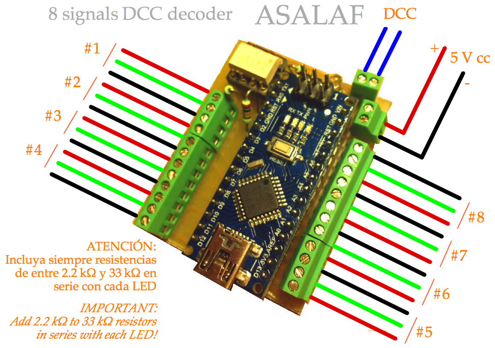
Este artículo muestra cómo convertir un simple Arduino Nano en un eficiente descodificador DCC para controlar hasta 8 señales de dos aspectos. El programa proporciona un bonito efecto de conmutación gradual, que apaga poco a poco la luz roja antes de encender progresivamente la verde, y al revés.


This page shows how to convert a simple Arduino Nano into an efficient DCC decoder for eight two aspect signals. The code is also able to perform a nice dimming effect, so red light fades slowly off before green light goes progressively on, and viceversa.

La lista de componentes es muy reducida, y todos ellos pueden conseguirse fácilmente:


The part list is quite reduced, and all components are easily found everywhere:

Lista de componentes

  • 1 x Arduino Nano 16 MHz 5V con USB
  • 1 x Optoacoplador 6N137
  • 1 x Led cualquiera
  • 3 x 10 kΩ resistencias de 1/8 W
  • Los conectores que se ven en las fotos (28 total)
  • 1 x placa de circuito impreso
   

Part list

  • 1 x Arduino Nano 16 MHz 5V with USB
  • 1 x Optocoupler 6N137
  • 1 x Led (any)
  • 3 x 10 kΩ resistor 1/8 W
  • Connectors shown in pictures (28 total)
  • 1 x printed circuit board


/* 2 x 8 dimming LEDs with Arduino Nano DCC decoder
   By German Trinidad and Norber, Spain, December 2015
   Freely distributable for private, non commercial, use

   Attach led anodes (+) to #1 to #8 outputs
   Attach all led catodes (-) to GNDs
   Don't forget to add serial resistors! */

#define ADR_MMAUS_01  129  // Assign here your addresses
#define ADR_MMAUS_02  130
#define ADR_MMAUS_03  131
#define ADR_MMAUS_04  132
#define ADR_MMAUS_05  133
#define ADR_MMAUS_06  134
#define ADR_MMAUS_07  135
#define ADR_MMAUS_08  136
#define ADR_MMAUS_09  137

byte comb[][4] = {
  //Address                      , Port                    , Pin-√ , Pin--
  {((ADR_MMAUS_01 - 1) / 4) + 128, ((ADR_MMAUS_01 - 1) % 4), 4     , 5   },
  {((ADR_MMAUS_02 - 1) / 4) + 128, ((ADR_MMAUS_02 - 1) % 4), 6     , 7   },
  {((ADR_MMAUS_03 - 1) / 4) + 128, ((ADR_MMAUS_03 - 1) % 4), 8     , 9   },
  {((ADR_MMAUS_04 - 1) / 4) + 128, ((ADR_MMAUS_04 - 1) % 4), 10    , 11  },
  {((ADR_MMAUS_05 - 1) / 4) + 128, ((ADR_MMAUS_05 - 1) % 4), 12    , 13  },
  {((ADR_MMAUS_06 - 1) / 4) + 128, ((ADR_MMAUS_06 - 1) % 4), 14    , 15  },
  {((ADR_MMAUS_07 - 1) / 4) + 128, ((ADR_MMAUS_07 - 1) % 4), 16    , 17  },
  {((ADR_MMAUS_08 - 1) / 4) + 128, ((ADR_MMAUS_08 - 1) % 4), 18    , 19  },
  {((ADR_MMAUS_09 - 1) / 4) + 128, ((ADR_MMAUS_09 - 1) % 4), 20    , 21  },
};

#define DCC_INT   2
#define SI        0
#define NO        1
#define TICKS    215           // Prescaler 8 -> Timer pulse every 0.5 µs -> 200 ticks are 100 µs
#define FREQ     120           // 15 ms aprox 
#define DELTA     3            // PWM
#define TO_OFF   20
#define PAUSE    30
#define TO_ON    40

volatile byte buf_dcc[6];
volatile byte pinPWM_1, pinPWM_2;
volatile boolean varyingLed = false;
volatile int duty = FREQ - 1;
volatile byte state = TO_OFF;

void setup() {
  for (int i = 4; i < 20; i++) {
    pinMode(i, OUTPUT);
    if (i & 0x01) digitalWrite(i, LOW);      // Green leds at odd pins start off
    else digitalWrite(i, HIGH);              // Red leds at even pins start on
  }
  pinMode(DCC_INT, INPUT);
  Serial.begin(9600);
  Serial.print("Iniciando...");
  delay(500);
  attachInterrupt(0, dcc_int, CHANGE);       // pin2 = DCC      externalInterrupt 0
  cli();
  TCCR0A = 0;
  TCCR0B = 0;
  TCCR0B |= (1 << CS01);                     // Set CS01 bit for 8 prescaler (0.5 µs) on Timer0 - DCC
  TCCR2A = 0;
  TCCR2B = 0;
  TCCR2B |= (1 << CS21);                     // Set CS21 bit for 8 prescaler (0.5 µs) on Timer2 - Dimming
  TIMSK2 = 0;
  TIMSK2 |= (1 << TOIE2);                    // Enable Timer2 Overflow interrupt
  sei();
}

void dcc_int() {                               // ISR(INT0_vect) External interrupt routine for signal on pin2
  static int tmp_pulse;                        // German is a genius!
  static byte bit_dcc;
  static byte preamb;
  static byte aux_dcc, x_or, idx, num_bits;

  if (PIND & (0x04)) TCNT0 = 0;
  else  {
    tmp_pulse = TCNT0;
    if (tmp_pulse > TICKS) bit_dcc = 0;
    else bit_dcc = 1;
    if (preamb == SI) {
      if (bit_dcc) {
        if (num_bits) num_bits--;
      }
      else {
        if (!num_bits) {
          preamb = NO;
          num_bits = 9;
          x_or = 0;
          idx = 0;
        }
        else num_bits = 10;
      }
    }
    else {
      if (--num_bits) aux_dcc = aux_dcc * 2 + bit_dcc;
      else {
        if (!bit_dcc) {
          buf_dcc [idx++] = aux_dcc;
          x_or ^= aux_dcc;
          num_bits = 9;
        }
        else {
          preamb = SI;
          num_bits = 10;
          if (x_or == aux_dcc) {                        // Data received OK!
           Serial.print(buf_dcc[0]);
            // buf_dcc[0] is Address
            // buf_dcc[1] is Port and command
            if (!varyingLed) {                          // While commuting, ignore commands
              byte port = (buf_dcc[1] & 0x06) >> 1;     // 0x06 = B0000 0110
              for (int i = 0; i < 9; i++) {
                if ((buf_dcc[0] == comb[i][0]) && (port == comb[i][1])) { // It's ours
                  if (buf_dcc[1] & 0x01) {
                    pinPWM_1 = comb[i][2];              // Pin to dim off
                    pinPWM_2 = comb[i][3];              // Pin to dim on
                  }
                  else {
                    pinPWM_1 = comb[i][3];
                    pinPWM_2 = comb[i][2];
                  }
                  if (digitalRead(pinPWM_1)) {          // Needs to be dimmed off indeed
                    varyingLed = true;
                    duty = 255;
                    state = TO_OFF;
                  }
                  return;
                }
              }
            }
          }
        }
      }
    }
  }
}

ISR(TIMER2_OVF_vect) {                         // Timer2 Overflow interrupt every 128 µs for dimmming leds
  if (varyingLed == true) {
    static int cont;
    cont++;
    switch (state) {
      case TO_OFF:
        if (cont == FREQ) {                    // High pulse starts when 'cont' reaches FREQ
          digitalWrite(pinPWM_1, HIGH);
          cont = 0;
          duty = duty - DELTA;
        }
        if (cont == duty) {
          digitalWrite(pinPWM_1, LOW);         // And ends when 'cont' reaches 'duty'
          if (duty < DELTA) state = PAUSE;
        }
        break;
      case PAUSE:
        if (cont == 5 * FREQ) {                 // Small dramatic pausae
          state = TO_ON;
          duty = DELTA;
          cont = 0;
        }
        break;
      case TO_ON:
        if (cont == FREQ) {
          digitalWrite(pinPWM_2, HIGH);
          cont = 0;
          duty = duty + DELTA;
          if (duty > 255 - DELTA) varyingLed = false;  // We're done
        }
        if (cont == duty) {
          digitalWrite(pinPWM_2, LOW);
        }
        break;
    }
  }
}

void loop() {
}


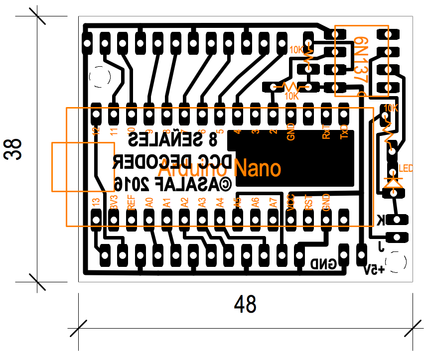
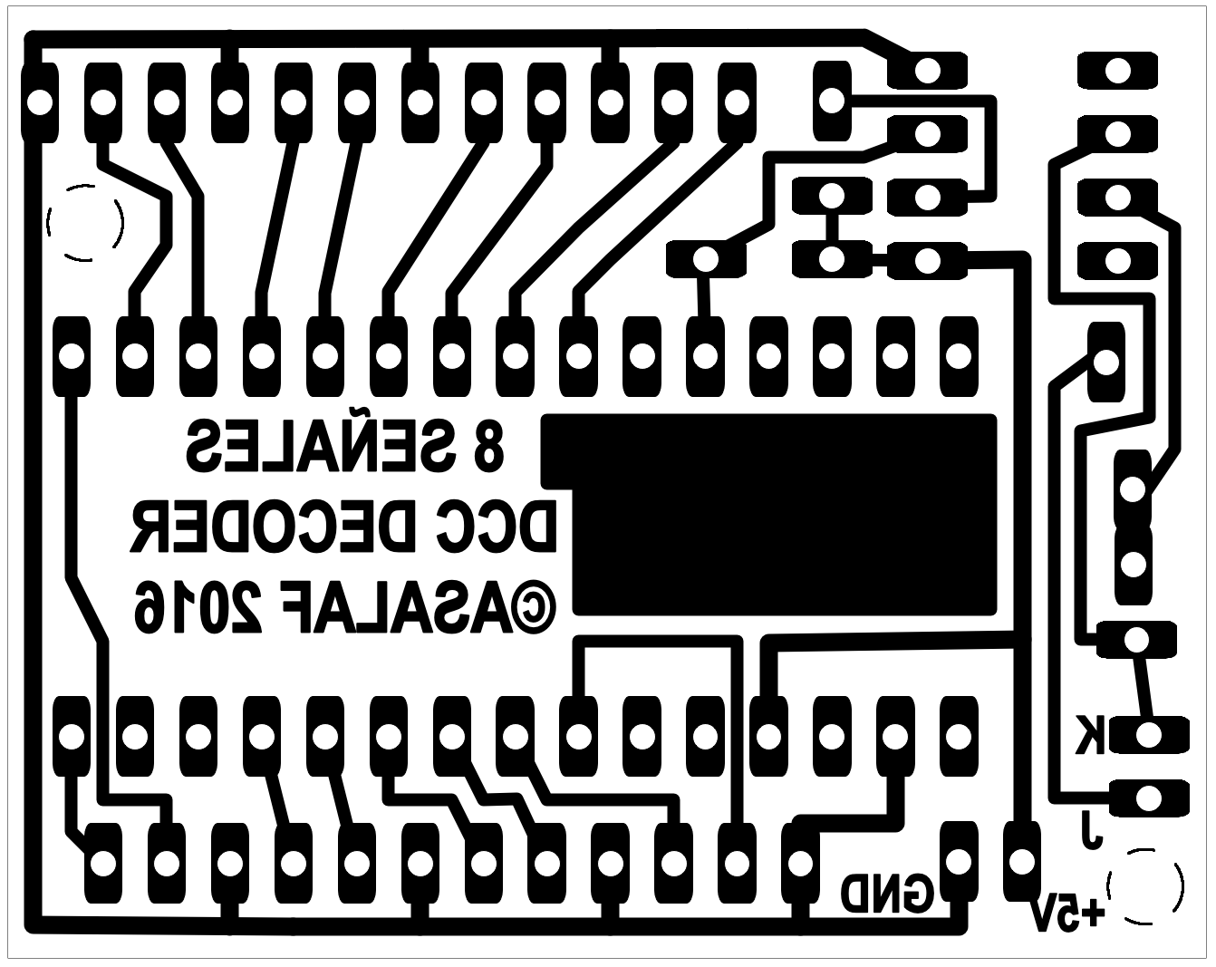
Prepare la placa de circuito impreso, suelde los componentes y programe el Arduino con el código de arriba (copiar y pegar en el Arduino IDE bastará).


Prepare the PCB, sold the components in place and program the Arduino whit the code below (just copy from this page and paste on Arduino IDE).

IMPORTANTE:


IMPORTANT:

No olvide añadir resistencias en serie con cada LED. Recomendamos resistencias de 1/8 W entre 2.2 kΩ y 33 kΩ, dependiendo de la eficiencia de los LEDs elegidos. Si no las coloca puede destruir para siempre el microcontrolador.


Don't forget to add resistors in series with each LED. We use 1/8 W resistors ranging from 2.2 kΩ to 33 kΩ, depending on the efficacity of the chosen LEDs. If you fail to add these resistors you may destroy the microcontroller for ever.

Este descodificador responderá a las direcciones de accesorios que escriba al principio del programa. Por ejemplo,  #define ADR_MMAUS_01 129 significa que la señal conectada en la posición #1 obedecerá a las órdenes dadas para el accesorio 129 y así.

  The accessory addresses this decoder will respond to are written at the beginning of the code. For instance, #define ADR_MMAUS_01 129 means that the signals attached to #1 will be controlled by address number 129 and so on.

Este programa ha sido diseñado para las centrales DCC de tipo Lenz / Roco Multimaus. Con otros sistemas las direcciones a programar pueden variar (pueden estar como adelantadas 4 posiciones, de forma que la #129 sería la #125 -o quizá es al revés... Nunca me acuerdo, lo siento!). Haga sus pruebas. Es facilísimo.


This code has been prepared for Lenz / Roco Multimaus type DCC command stations. With other systems the addresses may vary (they may be shifted 4 places down, so #129 is #125 -or maybe the opposite... I never remember, sorry!) . Do your tests. It's easy!

ASALAF_S88_Feedback_Module.png

ARDUINO COMO RETROMÓDULO S88

Es muy sencillo construir un retromódulo S88 utilizando un Arduino Uno. De hecho cualquier Arduino serviría, pero en aras de la simplicidad vamos a utilizar un Arduino Uno.

Hay que cargar el programa en el Arduino, conectarle 5 cables, alimentarlo y ya está funcionando.


ARDUINO AS S88 FEEDBACK MODULE

It is very easy to create a S88 feedback module using an ubiquitous Arduino Uno. In fact, any Arduino would serve well, but for the shake of simplicity we'll be using an Arduino Uno.

Upload the code, connect 5 wires to the indicated Arduino ports, power the module and that's all.

CABLEADO

S88
CLOCK
LOAD_PS
DATA_IN
DATA_OUT
GND

Sensores
Pines 8 a 13
Pines A0 a A5


WIRING

Arduino
pin 3
pin 4
pin 5
pin 6
GND

Sensors
Pins 8 to 13
Pins A0 to A5

Como la mayoría de los retromódulos S88 existentes, cada sensor se activa cuando su pin correspondiente se pone a potencial de masa (se conecta a GND)  

Like most S88 feedback modules, each sensor will be activated when its corresponding pin is put LOW (connected to GND).

EL PROGRAMA

Copie y pegue en Arduino IDE o descargue el archivo de más abajo.


THE CODE

Copy and paste into Arduino IDE or download the file .ino bellow.


/* Arduino as S88 feedback module with address assignment
 
 Code by German and Norber, Spain, November 2015.
 http://eliberia.es/digital
 Freely distributable for private, non commercial, use.
 
 Connections for S88 bus:
 s88 pin 1   DATA     to   ARD pin DATA_IN from previous Arduino in S88 chain
 s88 pin 2   GND      to   ARD GND
 s88 pin 3   CLOCK    to   ARD pin CLOCK,   externalInterrupt 1
 s88 pin 4   LOAD_PS  to   ARD pin LOAD_PS, pinChangeInterrupt
 s88 pin 6   Vdd+     to   ARD Vin
 s88 pin 1   DATA     to   ARD pin DATA_OUT from next Arduino in the S88 chain
 Note: The 'S88 chain' is defined from the last feedback module to the PC-interface
 
 12 occupancy sensors (activated when the pins are connected to GND):
   Pins 8 to 13   (six first sensors)
   Pins A0 to A5  (six last sensors)
 */

#define NUM_S88   0           // Number assigned to the first sensor reported from this feedback module
#define CLOCK     3           // Connect S88 CLOCK signal to Arduino pin3  - don't change this
#define LOAD_PS   4           // Connect S88 LOAD_PS signal to Arduino pin4
#define DATA_IN   5           // Connect S88 DATA from next S88 feedback module to Arduino pin 5
#define DATA_OUT  6           // Output DATA to next S88 feedback module or the PC interface to Arduino pin6


void setup() {
  pinMode(LOAD_PS, INPUT);
  pinMode(CLOCK, INPUT);
  pinMode(DATA_IN, INPUT);
  pinMode(DATA_OUT, OUTPUT);
  digitalWrite(DATA_OUT, LOW);
  for (int i = 8; i < 20; i++) {
    pinMode(i, INPUT_PULLUP);
  }
  attachInterrupt(1, clockS88, RISING);                      // pin3 = CLOCK    externalInterrupt 1
}

void clockS88()  {                                           // Rising edge CLOCK signal interruption 
  static byte cont;
  static int data;
  if (PIND & (1 << LOAD_PS)) {                               // Let's load my sensors info
    data = ~(((PINC & 0x3F)<<6) + (PINB & 0x3F));            // Load my sensors in 'data' (6 lowest bits of B and C ports)
    data = data & 0x0FFF;
    cont = 0;                                                // Start counter of data transmited
  }
  if (cont == NUM_S88) {                                     // Our turn: let's empty / shift / fill 'data'
    if (data & 0x01) PORTD |= (1<< DATA_OUT);                // Put in DATA_OUT the state of bit 'data0'
    else PORTD &= ~(1 << DATA_OUT);             
    data = data >> 1;                                        // Prepare (shift) 'data' for the next cycle   
    if (PIND & (1 << DATA_IN)) data = data | 0x0800;         // Put DATA_IN value in bit 'data11'
    }
  else {                                                     // Not yet our turn: just pass from IN to OUT
    if (PIND & (1<< DATA_IN)) PORTD |= (1 << DATA_OUT);      // Put in DATA_OUT the value of DATA_IN
    else PORTD &= ~(1 << DATA_OUT);                         
    cont++;                                                  // Update counter to continue waiting
  }
}

void loop() {
}


CÓMO FUNCIONA

Con este programa el Arduino emula perfectamente un retromódulo S88 típico, y añade una función extra no disponible en los montajes habituales: el número que identificará a cada sensor en el ordenador no dependerá de la posición física que ocupe este módulo en la cadena de retromódulos, sino que es un parámetro programable con ciertos límites.

Varíe simplement la primera línea de código efectivo, que es la que dice


HOW IT WORKS

With this code the Arduino will perfectly emulate an usual S88 feedback module, plus an extra feature usually not available in common feedback modules: the number each sensor will obtain from the computer is no necessarily dependent on the physical position this module occupies in the S88 chain, but will be a programmable parameter within certain limits.

Just vary the first line of effective code, the one saying 

#define NUM_S88 0


y substituya el 0 por el número de sensores que quiere que precedan a estos nuevos sensores en la cadena del S88.  

and substitute the 0 for the number of sensors you want to precede these new sensors in the S88 chain.

     
Por ejemplo: si ya tiene 2 retromódulos informado de, digamos, 16 sensores cada uno, su ordenador estará identificando probablemente el primero como sensor número 0 y el último como sensor número 31. Si quiere que su nuevo retromódulo Arduino aparezca como 'insertado' entre esos dos retromódulos preexistentes, pero sin tener que recablear el bus S88 para insertar físicamente el Arduino entre ambos, entonces puede conectar el Arduino al principio de la cadena (entre la interface con el ordenador y el primer retromódulo), y programarlo para 'dejar pasar' los primeros 16 sensores antes de informar de sus 12 propios. Es decir, puede asignar el 16 a NUM_S88.  

For example, if you already have 2 feedback modules reporting, let's say, 16 sensors each, your computer is probably identifying the first sensor as number 0 and the last one as number 31. If you want your new Arduino S88 feedback module to appear as 'inserted' between those two existing modules, but without the need of re-wiring your S88 bus as to physically insert it in between, you may connect the Arduino at the beginning of the chain (just next to the S88 interface to the computer), and program it to 'let pass' the first 16 sensors before reporting its 12 ones. That is, you may set the NUM-S88 as 16.

Entonces podrá ver sus primeros 16 sensores como de costumbre, pero los restantes 16 habrán sido desplazados 12 posiciones más atrás (empezarán ahora en el 28), porque el Arduino estará informando sobre sus nuevos 12 sensores como números 16 a 27. Es decir: ha sido insertado 'lógicamente' mientras que ha sido 'físicamente' conectado al final.  

Then you will see your former first 16 sensors as usual, but the remaining 16 sensors have been shifted 12 positions further (starting now from 28), because your Arduino is reporting the new 12 sensor it provides as numbers 16 to 27. That is: it has been 'logically' inserted while it's been 'physically' placed at the end.

Debido a la arquitectura inherente al bus S88 no es posible, sin embargo, más que desplazar 'lógicamente' hacia atrás los 12 nuevos sensores proporcionados por el Arduino, nunca hacia adelante.


Due to the inherent architecture of the S88 it is not possible, however, you can 'logically' shift backwards these 12 Arduino reported sensors, but never anticipate them.


Por ejemplo: en el caso de antes, si inserta 'físicamente' el Arduino entre sus retromódulos S88 existentes, puede programar el Arduino asignado 0 a NUM_S88, de manera que los sensores del Arduino ocuparán su posición física en el bus (desde la 16 a la 27) y el resto vendrá después (de la 28 a la 43).  Pero puede, sin embargo, asignar el valor 10 a NUM_S88, de forma que el módulo deje pasar la información de 10 sensores antes de informar sobre los suyos propios. Es decir, en el ordenador aparecerán 16+10=26 sensores antiguos en su sitio (del 0 al 25), luego 12 nuevos sensores (los del Arduino, números 26 a 37), y finalmente los 6 sensores restantes (del 38 al 43). Esto tiene como efecto desplazar 'lógicamente' hacia atrás 10 posiciones los nuevos sensores de Arduino. No intente programar un número negativo en NUM_S88: no funcionará!


For example: in the case above, if you 'physically' insert the Arduino between your two existing S88 feedback modules, then you may program the Arduino with NUM_S88 as 0, so Arduino sensors will be reported in its physical position (from 16 to 27) and the rest will come after (from 28 to 43). You may, however, set NUM_S88 as 10, so the module will let pass the information concerning 10 sensors before reporting the ones it controls. That is, you will get in the computer your 16+10 = 26 first old sensors in place (from 0 to 25), then 12 new sensors (from Arduino, numbers 26 to 37), and your remaining 6 sensors at the end (from 38 to 43). This has the effect to 'logically' shift backwards 10 positions the new Arduino sensors. Don't try to program a negative number in NUM_S88: it won't work!

IMPORTANTE


IMPORTANT

1. Si sitúa un Arduino al final del bus S88, entonces debe conectar su pin5 a masa (GND) para decirle al Arduino que no espere recibir ningún dato por ahí.


1. If you place an Arduino at the end of the S88 bus, connect pin5 to GND (as to tell Arduino it should not be expecting any data coming that way).

2. Los pines del Arduino envejecen y se estropean rápidamente. Si experimenta parpadeos de sensores en el ordenador mejore las conexiones.


2. Arduino pins tend to worn out very quickly. Improve connections if you experience flickering of sensors on your PC screen.

BIENVENIDO:

La tecnología Arduino a abierto una interesante puerta a la electrónica aplicada a la afición por el modelismo ferroviario.

En esta sección Vd. podrá encontrar algunos montajes para construir uno mismo. Los hay para maquetas analógicas (tradicionales), pero la mayoría han sido diseñados para maquetas digitales DCC. Y muchos son para XpressNet (el sistema europeo de Lenz, Fleischmann y Roco).


WELCOME:

Arduino technology has opened an interesting door to electronics applied to the hobby of model trains.

In this section you may find some nice devices you can do yourself at home. They can be used on analogic (traditional) layouts, but most of them have been designed for DCC. Many apply to XpressNet layouts (Lenz, Fleischmann, Roco european system).

Aquí abjo tienes varios artículos con aplicaciones y utilidades para aplicar a los trenes en escala H0 y N, siguiendo el estándar DCC:

  Here you will find several articles with applications and utilities to apply to trains in H0 and N scale, following the DCC standard:


Paso a Nivel / Railway Crossing

Decoder DCC 8 Señales / DCC Decoder 8 Signals

Arduino como Retromódulo S88 / Arduin as S88 Feedback Module

CIRCUITO LANZADERA (ANALÓGICO) / COMMUTER TRAIN CIRCUIT (ANALOGIC)  En breve / Soon.


COMPONENTES


THE COMPONENTS


VIDEO


THE VIDEO

     
Arriba  

On top

EL CÓDIGO FUENTE


THE MAIN CODE


/* Arduino Nano Pro as
  - WAV sound files player (24 kHz - 8 bit - mono)
  - 1 servo controller - variable speed -
  - 2 alternating common cathode led controller
 Using:
  - 2 current sensing occupancy detectors
  - 1 contact occupancy detector
  - 1 infrared occupancy detector
  - SD card reader
 
  Code by Norber, February 2016

  Freely distributable for private, non commercial, use.

  Connections:
  SD card  GND   to  GND common
  SD card  MISO  to  ARD pin 12
  SD card  SCK   to  ARD pin 13
  SD card  MOSI  to  ARD pin 11
  SD card  CS    to  ARD pin 10
  SD card  5Vcc  to  +5 V cc

  ARD pin 3      to  transistor driven 8 ohms 5V loudspeaker

*/


#include 
#include 
#include 

#define INIT         10
#define DETECTING    20
#define ALARMS_ON    25
#define LOWING_BAR   30
#define BAR_DOWN     40
#define LIFTING_BAR  50
#define ALARMS_OFF   60
#define ERROR_UNKN   90

#define SENSIB       10

#define PIN_K1       8
#define PIN_K2       6
#define PIN_K3       7
#define PIN_IR       2
#define PIN_SERVO    5
#define PIN_LED1     A2
#define PIN_LED2     A3
#define PIN_LED3     A4
#define PIN_LED_PCB  A1
#define PIN_SOUND    3   // Must be 3: OC2B is pin3 - used for playing 8-bit WAV

#define HYSTER       30000  // Interval between alarms and barriers
#define DOWN_POS     2400
#define UP_POS       4000
#define INCR_SV      5
#define VEL_SER      1
#define BLINK_DEL    15  // Led blinking rate

byte sysEst = INIT;
boolean k1St, k2St, k3St, irSt, bellsOn, ledsOn;
volatile int posObj, posNow;
volatile boolean servMoving;

TMRpcm player;

void setup() {
  pinMode(PIN_K1, INPUT_PULLUP);
  pinMode(PIN_K2, INPUT_PULLUP);
  pinMode(PIN_K3, INPUT_PULLUP);
  pinMode(PIN_IR, INPUT_PULLUP);
  pinMode(PIN_LED1, OUTPUT);
  pinMode(PIN_LED2, OUTPUT);
  pinMode(PIN_SERVO, OUTPUT);
  pinMode(10, OUTPUT);
  //Serial.begin(9600);
  if (!SD.begin(10)) {
    // Serial.println("SD card error");
    return;
  }
  //Serial.println("SD card OK");

  cli();
  TCCR0A = 0;
  TCCR0B = 0;
  TCCR0B |= (1 << CS02) | (1 << CS00);      // Set CS00 & CS02 bits for 1024 prescaler on Timer0 - LEDs
  OCR0A = 234;                              // Comp Match every 15 ms  (66.67 Hz)
  TIMSK0 = 0;
  TIMSK0 |= (1 << OCIE0A);                   // Enable Timer0 interrupts for Compare Match A

  TCCR1A = 0;
  TCCR1B = 0;
  TCCR1A |= (1 << WGM11);                    // Turn on Fast PWM mode
  TCCR1B |= (1 << WGM13) | (1 << WGM12);     // Turn on Fast PWM mode
  TCCR1B |= (1 << CS11);                     // Set CS11 bit for 8 prescaler (0.5 µs) on Timer1 - Servos
  ICR1 = 40000;                              // Set PWM fixed frequency (overflow every 20 ms)
  TIMSK1 = 0;
  TIMSK1 |= (1 << OCIE1A) | (1 << TOIE1);    // Enable Timer1 interrupts for Compare Match A & Overflow mode
  sei();                                     // Activar interrupciones

  player.speakerPin = PIN_SOUND;
  player.setVolume(1);
  player.volume(1);
  player.loop(1);
  player.play("Campo3.wav");
  sysEst = DETECTING;
  posNow = UP_POS;
}

boolean readSensors() {
  static int cntr, k1Count, k2Count, k3Count, irCount;
  static boolean result;
  k1Count += digitalRead(PIN_K1);
  k2Count += digitalRead(PIN_K2);
  k3Count += digitalRead(PIN_K3);
  irCount += digitalRead(PIN_IR);
  if (++cntr == SENSIB) {
    if ((k1Count == 0)||(k2Count == 0)||(k3Count)||(irCount == 0)) result = true;
    else result = false;
    cntr = 0;
    k1Count = 0;
    k2Count = 0;
    k3Count = 0;
  }
  return result;
}

void loop() {
  static unsigned int cntr;
  static boolean detection = readSensors();
  switch (sysEst) {
    case DETECTING:
      if (detection) {
        sysEst = ALARMS_ON;
      }
      break;
    case ALARMS_ON:
      if (bellsOn == false) {
        player.play("Bells1.wav");
        bellsOn = true;
        ledsOn = true;
      }
      if (++cntr == HYSTER) {
        sysEst = LOWING_BAR;
        posObj = DOWN_POS;
        servMoving = true;
        cntr = 0;
      }
      break;
    case LOWING_BAR:
      if (servMoving == false) {
        sysEst = BAR_DOWN;
      }
      break;
    case BAR_DOWN:
      if (detection == false) {
        if (++cntr == HYSTER) {
          sysEst = LIFTING_BAR;
          posObj = UP_POS;
          servMoving = true;
          cntr = 0;
        }
      }
      break;
    case LIFTING_BAR:
      if (servMoving == false) {
        sysEst = ALARMS_OFF;
      }
      break;
    case ALARMS_OFF:
      if (++cntr == HYSTER) {
        player.play("Campo3.wav");
        ledsOn = false;
        bellsOn = false;
        PORTC &= 0xF3;
        cntr = 0;
        sysEst = DETECTING;
      }
      break;
    case ERROR_UNKN:
      ledsOn = true;
      break;
  }
}

ISR(TIMER0_COMPA_vect) {                     // Timer0 Compare Match interrupt every 15 ms
  static int cntr;
  if (ledsOn && (++cntr == BLINK_DEL)) {
    if (PINC & 0x04) (PORTC &= 0xF3) |= 0x08;  // Toggle pinA2 and pinA3 alternatively
    else (PORTC &= 0xF3) |= 0x04;
    cntr = 0;
  }
}

ISR(TIMER1_OVF_vect) {                       // Timer1 Overflow interrupt for servo every 20 ms
  static int dif;
  if (servMoving == true) {
    dif = posNow - posObj;
    if (dif < 0) posNow += INCR_SV;
    else if (dif > 0) posNow -= INCR_SV;
    else servMoving = false;
    PORTD |= (1 << 5);                       // Servo is pin5
    OCR1A = posNow;
  }
}

ISR(TIMER1_COMPA_vect) {                     // Timer1 Match Compare A interrupt for servos
  PORTD &= ~(1 << 5);
}


ADD-ONS (LIBRERIAS Y OTROS ARCHIVOS)


THE ADD-ONS (LIBRARIES AND OTHER FILES)

     
Las cookies facilitan la prestación de nuestros servicios. Al utilizar nuestros servicios, usted acepta que utilizamos cookies.
Más información De acuerdo